Creality 3D Printers are notorious for having a warped heated bed. The Ender 3 and 5 series have it the worst, with seemingly zero quality control on what reaches the customers. Purchasing a glass plate has become almost a necessity, a band-aid fix to cover up underlying surface problems. With flatness tolerances ranging anywhere from +/- 0.3mm to an upwards of 1.0mm, it’s no surprise that many of these beds are practically unusable.
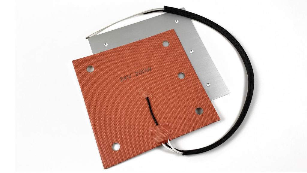
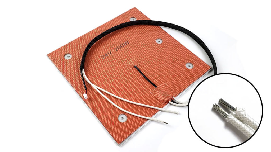
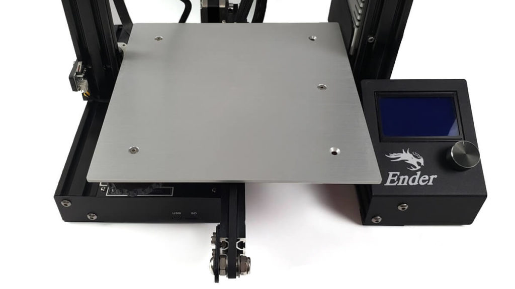
To address this, we’ll look at how to install the Gulfcoast Robotics Heated Bed Kit. It’s equipped with a precision CNC milled aluminum build plate, powerful 24V silicone heater, and all the conveniences to make it a simple drop-in upgrade.
Disclaimer: I work at Gulfcoast Robotics and have provided feedback in the design of this product. As this is my personal website however, the thoughts and opinions shared here are entirely my own.
Purchased Parts
235x235mm Heated Bed Upgrade - $59.99
Checking Build Plate Flatness
Most of us don’t have the tools needed to measure flatness tolerances, they are expensive. The good news is, there are a couple DIY methods to figure out if your heated bed is warped.
However, testing while it’s installed on the 3D Printer won’t give us accurate results. Tension on the corners from the bed leveling screws can heavily skew the shape. As such, make sure to remove it from the machine before trying these out.
Ruler Method
You probably have a standard 12″ ruler somewhere nearby, wood or metal will work. Since the edges of a ruler are fairly straight, we can lay it across the surface and check for high or low spots.
Place a light behind the ruler, look from the front (eye level with the bed) and see if any light is visible.
Countertop Method
Kitchen and bathroom countertops are often made from granite, marble or some sort of stone. These should be extremely flat and will serve well as a reference point for comparisons.
Lay the bed face down on the counter, then press on various spots to see if there is any flex or wobbles.
These aren’t perfect tests by any means, but they are quick and dirty checks that anyone can do. For the most part, they will give us a reasonably good idea if the build plate is anything less than flat.
Heated Bed Installation
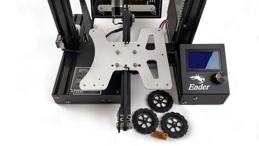
To get started, we first need to remove the original heated bed. Loosen the thumb wheels until they fall off, then set these and the leveling springs aside. Carefully lift the bed up from the Y axis and place it behind the 3D Printer for now.
Next we need to disconnect the bed from the board. Open the electronics case by removing the (3) hex screws on top, two in the front corners and one in the middle rear. With these out, you can lift the lid and set it aside, taking care not to stress the cooling fan wires.
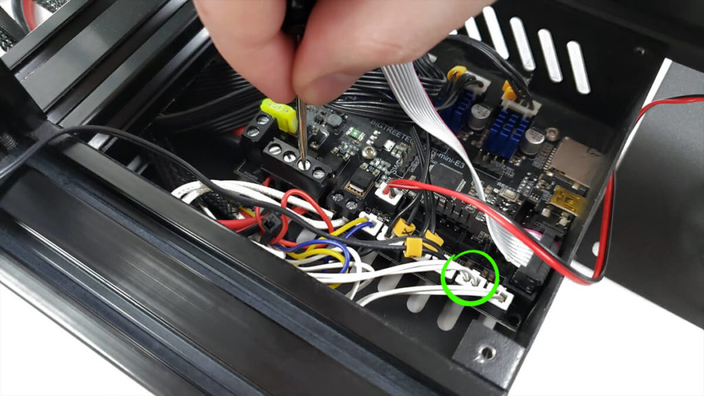
The bed’s (2) power cables are secured in a clamping terminal block. Using a small flat head screwdriver, loosen both set screws on top until the cables can freely slide out. While we’re in here, we also need to unplug the thermistor, the white 2-pin JST connector (circled below).
Pull the power cables and thermistor wiring out from the back of the Ender 3 to detach the heated bed.
With the original heated bed removed, we can start preparing our replacement for installation.
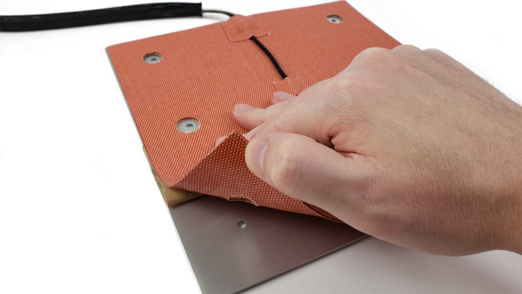
Flip the build plate over with the bottom side facing up (countersunk holes facing down). At this point, it’s a good idea to clean the surface with isopropyl alcohol, just to remove any greasy fingerprint oils before we attach the heater.
Now position the silicone heater so that the holes match up with the build plate. There is only one correct orientation due to the additional hole for optional 3-point leveling support. Once it’s aligned, peel back the protective 3M adhesive backing and start applying the silicone heater with firm pressure.
After the silicone heater has been mounted, we’re just about ready to install it on our Ender 3 / Ender 5 3D Printer. Before doing so however, we’ll take a quick look at the wiring.
The (2) white cables are for powering the heater. One comes pre-stripped while the other does not. Using wire strippers or a pair of scissors, strip off 1/2 inch of the insulation to match, exposing the wire strands for a solid connection.
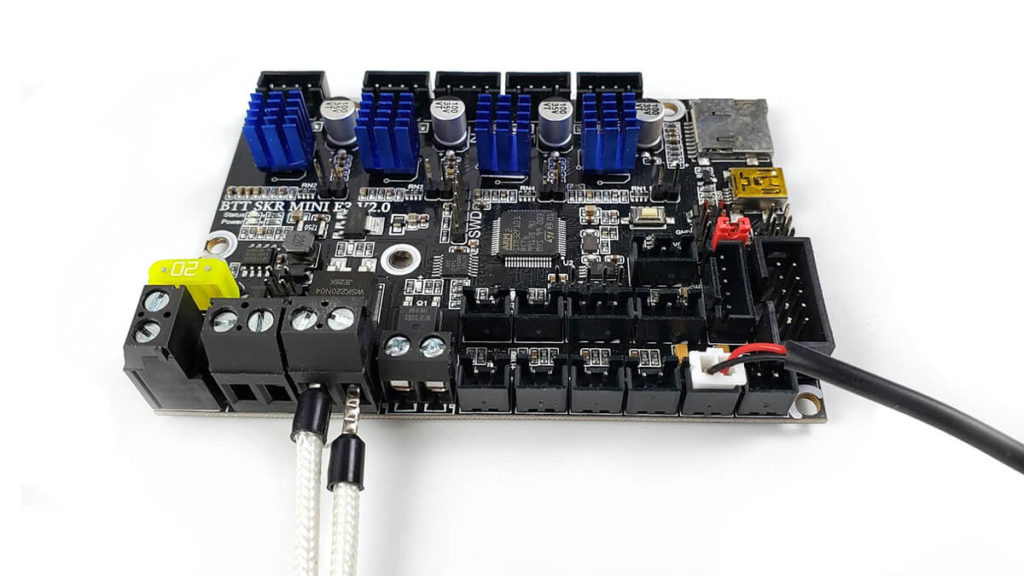
At this point, we’re ready to go ahead and start installing the new heated bed. For the sake of clarity, the connections are shown below on an empty board. Run the silicone heater’s power cables and thermistor wiring into the electronics case, routing them through the back of the lower frame.
The (2) white power cables are inserted into the HOTBED terminal block, then clamped down by tightening the set screws on top. In contrast to the original heated bed, there is no polarity with the silicone heater, meaning the cables have no +/- and are interchangeable. Give them a gentle tug to make sure they are properly seated.
The 2-pin JST thermistor connector plugs into the 2nd port from the right labeled THB.
With the silicone heater now wired up, the last step is mounting the heated bed.
As this kit does not come with additional hardware, we’ll reuse the M4x35mm bolts from the original build plate. Depending on the type of print surface it has, you may need to peel this up at the corners to reach them. At this point, everything goes back together the same way it came apart.
In my case, I am also using the Gulfcoast Robotics Y Carriage with a 3-Point leveling configuration. For those with the stock Y Carriage, ignore the center right hole and place a bolt, spring and thumb wheel at each of the 4 corners instead.
After we’ve wrapped up the installation, it’s time to test. Power on the Ender 3 and preheat the bed from the LCD menu. If everything is connected properly, it should start warming up.
Firmware Update
Flashing a firmware update is not necessary to use this product. However, adjusting the TEMP_SENSOR_BED value may offer slight improvements to the temperature readings.
Ender 3 firmware is configured to use a value of “1” (EPCOS) whereas this silicone heater works best with a value of “11” (NTC3950). As these are both 100K thermistors with 4.7K pull-up resistors, they have similar results, but the temperatures reported may be a few degrees off.
In the Marlin firmware Configuration.h file, locate the line “#define TEMP_SENSOR_BED” under the “Thermal Settings”. After this value is changed from “1” to “11”, recompile the firmware and flash it to the board.
//===========================================================================
//============================= Thermal Settings ============================
//===========================================================================
// @section temperature

/**
* --NORMAL IS 4.7kohm PULLUP!-- 1kohm pullup can be used on hotend sensor, using correct resistor and table
*
* Temperature sensors available:
*
*     0 : not used
*     1 : 100k thermistor - best choice for EPCOS 100k (4.7k pullup)
*     2 : 200k thermistor - ATC Semitec 204GT-2 (4.7k pullup)
*     3 : Mendel-parts thermistor (4.7k pullup)
*     4 : 10k thermistor !! do not use it for a hotend. It gives bad resolution at high temp. !!
*     5 : 100K thermistor - ATC Semitec 104GT-2/104NT-4-R025H42G (Used in ParCan, J-Head, and E3D) (4.7k pullup)
*     6 : 100k EPCOS - Not as accurate as table 1 (created using a fluke thermocouple) (4.7k pullup)
*     7 : 100k Honeywell thermistor 135-104LAG-J01 (4.7k pullup)
*     8 : 100k 0603 SMD Vishay NTCS0603E3104FXT (4.7k pullup)
*     9 : 100k GE Sensing AL03006-58.2K-97-G1 (4.7k pullup)
*    10 : 100k RS thermistor 198-961 (4.7k pullup)
*    11 : 100k beta 3950 1% thermistor (Used in Keenovo AC silicone mats and most Wanhao i3 machines) (4.7k pullup)
*    12 : 100k 0603 SMD Vishay NTCS0603E3104FXT (4.7k pullup) (calibrated for Makibox hot bed)
*    13 : 100k Hisens 3950  1% up to 300°C for hotend "Simple ONE " & "Hotend "All In ONE"
*/
#define TEMP_SENSOR_0 1
#define TEMP_SENSOR_BED 1
Further Improvements
For most owners, a precision milled CNC plate with tight flatness tolerances will be more than enough. This solves the biggest problem with Ender 3 and Ender 5 3D Printers, a bowed print surface. We can however take this a step further with other heated bed upgrades.
3-Point Leveling
You might have noticed the Gulfcoast Robotics Heated Bed supports 3-Point bed leveling. This is an entirely optional feature, but one that improves the leveling process as a whole.
Back in grade school, geometry class taught us that a plane is defined by 3 points. So why does almost every 3D Printer come with 4 point leveling? Manufacturers like Creality know their beds are warped, but adding an extra leveling point can force it into a semi-flat, somewhat usable shape.
3-Point Leveling won’t fare well with a warped bed for obvious reasons, but that’s not a problem with this ultra flat build plate. We do however need a compatible Y Carriage plate to take advantage of this feature.
Heated Bed Insulation
The silicone heater preheats faster than the original circuit board heater (PCB), but what if we could speed that up even more, cutting it down to a fraction of the time?
Since heat rises, most of the warmth gets transferred into the build plate, but we can still lose a lot of it from the bottom. By insulating the underside, we can trap the heat and force it to rise as well. This will decrease the duration it takes to reach and maintain temperature.
Corkboard
Cork is a tried and true material for insulating heated beds. It’s cheap, environmentally friendly and withstands temperatures up to 140C. Corkboard tiles average around $1 each and can be mounted using a variety of adhesives.
Foam Foil
A more recent addition to the market, Foam Foil is a decent alternative that’s ready made for 3D Printers. It’s lightweight and heat resistant, plus it comes with a pre-applied adhesive backing. You still have to cut holes for the bed leveling screws, but it’s otherwise ready to use.
Great article, I am thinking of purchasing one of these kits, as my Ender 3 came with a warped bed, and I have been using a glass bed to compensate. I have also been using a “stick on” PEI sheet on the glass to hold the prints firmly – (works too well sometimes). What would you recommend to put on the build plate to print on?.
I’ve used a combination of glass with PEI on top for many years, it’s still among my favorites. If the heated bed is actually flat though, magnetic flex plates are an excellent choice. Not the cheap ones that Creality has started using, they wear out fast, but rather spring steel with a PEI powder coated surface. You just remove the plate, bend it and the print pops off.
Thanks for the feedback! I still have a bit more content to add here over the weekend. I’m going to look at insulating the heater for faster warmup times, as well as various build surfaces.
-Brett
can you recommend a good how-to guide for configuring marlin for a first time firmware editor?
i’ve downloaded VSCode and the marlin autobuild extension for it, but i dont know where to go from here – and the creality printer groups on fakebook are all but useless unless you need help leveling your bed.
any advise would be greatly appreciated.
Hi Berne,
What aspect of the process are you looking for information on, compiling or configuring?
I can’t say that I have seen many guides, but as for configuring it, the Configuration.h contains all of the notable settings and it’s well documented. You can also check the Marlin website, where they have pretty extensive documentation. You generally won’t need to edit anything other than that one file unless it’s something very specific.
In regards to compiling it, I personally find it easier to bypass Visual Studio / VSCode entirely. Having used this software for close to 20 years, it always seems to get hung up on missing libraries and other various problems. For the SKR Mini E3 boards, I just use PlatformIO straight from the command line, rather than relying on VSCode to automate it. With that approach, I just go into the firmware directory, open a command prompt, type “platformio” with my desired parameters and it dumps out a BIN file I can place on the SD card.
I could potentially write a guide on whatever aspect you’re interested in, although I have been building a simple web-based firmware compiler tool. It was placed on the backburner during the holidays, but I will probably wrap it up and push it live here in the next week or two.
-Brett
at least for now i’m mostly looking for information on configuring, and then probably compiling. because i’m very new to all of this (modifying firmware, vs just using/installing pre-compiled stuff) – and its been almost 25 years since i took my OOP/c/c++ classes in college and realized i hated looking for a missing ; in the code and switched career paths lol
Mostly right now what i *think* i need is where to look for the bits of data i’ll need to enable/disable from the default marlin 2.0.x firmware to get running on both my machines.
Ive got an ender 5 pro with GCR Bed/silicone heating mat & the stock creality 4.2.2 board and just received my 2nd GCR bed/silicone heater to bring my 3 pro back to life too (stock board tried to catch on fire, yikes!) so i havent even cracked the case on that one to see which board is in there yet.
ive currently got the stock firmware on the 3 pro, and running the creality Ender-5 Pro- Marlin2.0.1 – V1.0.1 – Endstop (sept 2020 version) that i had to update to so that i could remove the TCM communication error.
I used this YouTube channel to get through my first firmware compiling exercise, it was easy to follow and went smoothly. https://youtube.com/c/3DPrintscape
Looking forward to the bed coming back into stock so I can pick one up
Did you have any issues with the wires for the gulf coast heated bed getting in the way of the y axis motor?
Hi Chad,
A strain relief tab was added to the rear center of the build plate maybe 4-5 months ago. Prior to that, printed brackets like this were commonly used, but the integrated strain relief makes it much easier. You can just zip tie the centered silicone heater wiring to the tab, where that will keep it lifted and away from the Y axis motor.
-Brett
Recently installed VSCode +plugins and all working after Arduino IDE was failing in Windows 10.
(VSCode + PlatformOI/Auto Build Marlin plugins)
All within VSCode, edit the configuration.h file then use the Auto Build plugin to Build & Upload.
Three clicks to: open the Marlin Auto Build plugin, click Build & click Upload.
(any compile errors are shown in the console output for easy CLI like reference.)
Installing Marlin (PlatformIO)
https://marlinfw.org/docs/basics/install_platformio.html
PlatformIO in VSCode (+Auto Build Marlin)
https://marlinfw.org/docs/basics/install_platformio_vscode.html
Depending on the installed board, you will need to reference pre-tested marlin configurations on their GitHub site:
https://github.com/MarlinFirmware/Configurations/tree/release-2.0.9
Creality / Ender specific configuration example files:
https://github.com/MarlinFirmware/Configurations/tree/release-2.0.9/config/examples/Creality
A bit late but may help others looking for VSCode build info.
-Shane
Hi Shane,
Thank you for sharing this, fantastic information.
For those that dislike or struggle with Virtual Studio, it can potentially be omitted. I installed PlatformIO Core standalone on Windows 10 and just run the build from command line. Navigate to the Marlin directory where the “platform.ini” file is located, type “cmd” in the top bar, then run “platformio run -e STM32F103RC_btt_maple”, replacing the last part with whatever the board type is.
You do however have to add PlatformIO to the environmental PATH variable as explained here.
-Brett
If anyone is using both this heated bed and the 3-pint leveling Y carriage on an Ender 3v2, could you post a picture of the power cord setup? I can’t figure out how to get this situated without the cable (or the zip ties holding it in place) hitting the Y stepper motor and raising the bed… Also, raising the bed to a high enough point to keep from hitting the stepper motor makes the leveling knobs/wheels feel VERY loose
Having just addressed this myself a few days ago, the easiest solution is to upgrade your bed springs (link). Silicone heater wiring creates a bulge and needs more clearance on the V2, otherwise it can get stuck on the Y motor cover.
I have no idea why Creality went back to the cheap silver springs on the Ender 3 V2. They don’t keep the bed level for long and can get very loose. The yellow springs do a much better job of maintaining bed level and allow you to raise it higher with no issue.
-Brett
I had the same problem. Ultimately I did away with the springs and solid mounted the bed to help get the height needed to clear the stepper. Check out this video.
https://www.youtube.com/watch?v=sJ65-xLlna4
Is there a way to change the temp settings with out compiling your own firmware. Something I can do using a terminal?
has anyone had experience with changing the bed temperature settings to read more accurately with klipper thanks
I know this is a much older article, but I wanted to ask if you’ve had any long term problems on your SKR Mini board with the bed MOSFET. It looks like this heater exceeds the max power dissipation of the MOSFET by about 30W.
I’m getting ready to install a new bed with this heater and the same board on my E3 Pro and just wondered if I need to consider an external MOSFET or not.
David, it just so happens I have a stock Ender3 V1 dismantled to replace the V-wheel tyres, its late enough to have the extra holes for a 40mm wide Y axis [like the Ender3-Pro], but its at least three years old.
The stock heated bed on this machine is 220W, I have an Ender3 Pro with an SKR mini E3 and the only thing that fried was the X axis stepper driver when the fan got blocked and the board overheated – but that was definitely MY fault.
Whereas this silicone heater is 200W, so I think you’ll be OK [I haven’t gone through the process of checking the part ratings on the SKR tho.]
I recently purchased this upgrade for an Ender 3 Pro with 4.2.2 board. After updating the firmware using Marlin 2.1.2 according to these instructions, the bed temp is reading a full 15 degrees C low with an infrared thermometer. The temp is consistent over the bed, usually about +- 2 or 3 degrees, but if I set the bed temp to 70, and after letting the bed get to temp and waiting about 5 minutes, the bed temp reads ~55 with the infrared thermometer. If I take a reading on the bottom side (heating pad itself) the temp is a couple degrees warmer but nowhere near 70. I noticed in Marlin 2.1.2 there are many more options for thermistors than in the image in this post. I was wondering if a different value for TEMP_SENSOR_BED might be better with the new version, or if I might have a wonky unit.
What happened to Gulfcoast Robotics? Ordered over $300 in kits, only thing I could use was the bed due to missing parts. No response to emails, had to file a dispute with PayPal. Cost for the kits with the missing parts was refunded all I wanted was the missing parts. Now the site is dead.